ASTM E2246 Thin Film Strain Gradient Testing by Optical Interferometry
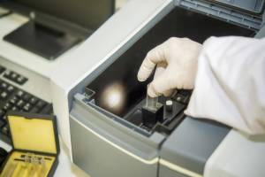
The ASTM E2246 test method determines the strain gradient of thin, reflecting films in microelectromechanical systems by a non-contact optical interferometric microscope that can form topographical 3-D data sets. This optical interferometric microscope does not record readings from the cantilevers touching the underlying layer.

TRUSTED BY


Precision-driven testing for dimensional accuracy and compliance
- Overview
- Scope, Applications, and Benefits
- Test Process
- Specifications
- Instrumentation
- Results and Deliverables
Overview
ASTM E2246 provides the standard guide for measuring strain gradients in thin films deposited on substrates using optical interferometric microscopy. Strain gradients arise from residual stress variations across the film thickness, causing suspended or released thin-film structures to curl or deflect out of plane. Interferometric measurement of this curvature provides quantitative data on the magnitude of the strain gradient.
Strain gradient characterization is essential for MEMS device design, reliability, and process control, as residual stress gradients can cause unacceptable deflection in cantilevers, membranes, and suspended structures, thereby compromising device functionality.

Scope, Applications, and Benefits
Scope
ASTM E2246 evaluates:
- Out-of-plane deflection of released thin film structures
- Strain gradient (κ, m⁻¹) calculated from cantilever tip deflection
- Effect of deposition conditions on strain gradient
- Spatial distribution of strain gradient across a wafer
Applications
- MEMS cantilever, bridge, and membrane process qualification
- Thin film deposition process optimization (PVD, CVD, ALD)
- Semiconductor packaging stress analysis
- Micro-mirror and actuator fabrication quality control
- Research and development of low-stress thin film systems
Benefits
- Non-contact, full-field strain gradient mapping
- No sample destruction or specialized mechanical testing required
- Rapid characterization across multiple structures on a wafer
- Provides process feedback for stress gradient control
- Supports MEMS design validation against curvature specifications
Test Process
Structure Preparation
Released thin film cantilever or bridge test structures (fabricated on the wafer or from a standard MEMS test chip) are used; dimensions are verified by optical microscopy before measurement.
1Interferometric Imaging
The released structures are imaged by white-light or phase-shifting interferometry to acquire a 3D height map showing the out-of-plane deflection profile along cantilever length.
2Deflection Profile Extraction
Height profiles along the cantilever length are extracted from the interferometric map; the deflection at the tip relative to the anchored end is measured.
3Strain Gradient Calculation
Strain gradient κ is calculated from the relationship between tip deflection, cantilever length, and film thickness; results are reported with uncertainty per ASTM E2246 guidelines.
4Technical Specifications
| Parameter | Details |
|---|---|
| Applicable Structures | Released thin film cantilevers, bridges, membranes |
| Vertical Resolution | <1 nm (white-light interferometry) |
| Strain Gradient Range | 0.1 m⁻¹ to >1000 m⁻¹ |
| Film Materials | Metals, oxides, nitrides, polymers, poly-Si |
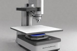
Instrumentation Used for Testing
- White-light interferometric microscope (Zygo, Bruker/Veeco)
- Anti-vibration optical table
- Calibrated vertical reference artifact
- MEMS test structures or dedicated cantilever test chips
- Surface analysis and profile extraction software
Results and Deliverables
- 3D interferometric height maps of released structures
- Cantilever tip deflection profile
- Calculated strain gradient κ (m⁻¹) with uncertainty
- Wafer map of strain gradient distribution (if multiple sites measured)
- Process trend data for deposition parameter optimization
- Full measurement report per ASTM E2246
Why Choose Infinita Lab for ASTM E2246?
At the core of this breadth is our network of 2,000+ accredited labs in the USA, offering access to over 10,000 test types. From advanced metrology (SEM, TEM, RBS, XPS) to mechanical, dielectric, environmental, and standardized ASTM/ISO testing, we give clients unmatched flexibility, specialization, and scale. You’re not limited by geography, facility, or methodology—Infinita connects you to the right testing, every time.
Looking for a trusted partner to achieve your research goals? Schedule a meeting with us, send us a request, or call us at (888) 878-3090 to learn more about our services and how we can support you. Request a Quote
Frequently Asked Questions
Strain gradients arise from through-thickness variations in residual stress caused by composition gradients, deposition rate changes, temperature gradients during deposition, grain size variation, or phase transitions through the film thickness. Even nominally uniform deposition processes often produce some degree of strain gradient.
Strain gradient causes cantilevers, mirrors, and suspended beams to curl out of plane upon release from the substrate. This deflection changes the gap distance in capacitive sensors, misaligns optical MEMS mirrors, and can prevent reliable contact in RF MEMS switches — all critical functional failures.
For a cantilever of length L and film thickness t, the tip deflection δ ≈ κL²/2, where κ is the strain gradient. This simple beam relationship allows κ to be extracted from interferometrically measured tip deflection, provided the cantilever length and film thickness are known accurately.
Un-released films cannot deflect freely, so direct cantilever-based strain gradient measurement requires released structures. For attached films, wafer bow measurement (ASTM F1390) measures the average biaxial stress but cannot separately determine the strain gradient profile through the thickness.
Strategies include optimizing substrate temperature during deposition, using two-layer film stacks with opposing stress gradients, post-deposition annealing, adjusting deposition pressure and power, and using ALD for superior through-thickness uniformity.


Request a Quote
Submit your material details and receive testing procedures, pricing, and turnaround time within 24 hours.
 Quick Turnaround and Hasslefree process
 Confidentiality Guarantee
 Free, No-obligation Consultation
 100% Customer Satisfaction
