Researchers can examine the nanoscopic world with amazing depth and resolution using a scanning electron microscope (SEM), a potent imaging tool. High-resolution photographs of a sample's surface are produced using a focused electron beam.
Modern semiconductors and integrated circuits have geometries measured in angstroms and nanometers, making flaws invisible to the naked eye. The ultimate goal of failure analysis is to generate a crystal-clear, indelible snapshot of a defect’s existence. A good image can help determine the corrective action needed to address persistent issues. However, modern integrated circuits are constructed with geometries measured in angstroms and nanometers, far below the resolution threshold of optical microscopy. Large defects, such as those caused by severe electrical overstress, can be seen clearly under an optical microscope, making flaws in these devices almost undetectable.
Electron microscopy uses powerful electromagnetic fields to create, shape, and focus an electron beam onto a sample’s surface. The electron microscope’s diffraction limit is smaller, allowing for resolutions of several angstroms. This improved resolution can be used to discover nanoscale flaws like crystalline dislocations or gate oxide pinholes.
Tuning the electron microscope detector to collect secondary or mostly backscattered electrons can produce different data, highlighting elemental variations or inferred topography. The depth of field of electron microscopes is greater than that of optical microscopes, allowing for the inspection of large three-dimensional structures over extended distances.
In addition to producing secondary and backscattered electrons, electron microscopy also produces distinctive x-rays due to the excitation and relaxation of electrons orbiting the sample’s atoms. An energy dispersive spectrometer (EDS) can gather these x-rays and determine the material composition of the sample. EDS can accurately measure an alloy’s contents for comparison to a standard or create an elemental “map” to illustrate concentrations on a sample.
Electron microscopy can be used as an isolation technique for identifying flaws in various types of materials. The negatively charged electrons in the beam exhibit attraction, repulsion, and dispulsion depending on the sample’s charge. By applying a charge, such as a voltage source, the electron beam can alter its interaction with the sample, resulting is in picture contrast that can highlight defects. This method, also known as “charge contrast” or “focused contrast,” is useful for identifying anomalies, especially those leading to open circuits. Some flaws might not require additional setup, and analysts might be able to spot flaws just by looking at the passive charge contrast the electron beam produces.
Electron microscopy is essential for examining various anomalies, from molten silicon to broken metallization. However, it is crucial to ensure that the electron microscope image accurately represents the defect that caused the failure.

Liquid Chromatography-Mass Spectroscopy Liquid Chromatography-Mass Spectroscopy (LC-MS) is an analytical technique that allows the separation, identification, and quantification of the...
Read Article ➙
Highly Accelerated Stress Test - HAST Testing Services A highly accelerated stress test (HAST) is an essential part of environmental...
Read Article ➙
Introduction Accelerated aging in product testing is a methodology that simulates the long-term effects of environmental factors on a product...
Read Article ➙In-depth examination of genuine material testing solutions

EELS analysis of gate and channel is performed on fin field-effect transistors (finFETs). Scanning transmission electron...
Read Case Study
Introduction PVC is the polymer primarily used to make pipes for plumbing, drainage, and electrical conduits....
Read Case Study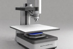
Nano-scale surface roughness is a critical parameter in fabricated thin-films that are used in optics, solar...
Read Case StudySubmit your contact info and we’ll get back to you within 24 hours

