ASTM E228: Linear Thermal Expansion (CTE) Testing via Dilatometry
ASTM E228 specifies the method for obtaining linear thermal expansion coefficient of rigid solids using a push-rod dilatometer. A rigid solid has negligible creep or elastic strain effects. This test is used in thermal modelling, design of equipment and components handling wide variation in operating temperatures, quality control and development of new materials for thermal applications.

TRUSTED BY


Precision-driven testing for dimensional accuracy and compliance
- Overview
- Scope, Applications, and Benefits
- Test Process
- Specifications
- Instrumentation
- Results and Deliverables
Overview
ASTM E228 is a standardized technique for determining the amount of rigid solid materials’ expansion with heat using push-rod dilatometry. It is usually used for materials that have a linear coefficient of thermal expansion above 0.5 µm/m·°C.
The basic principle is quite simple: when the sample is heated, it expands in length. This expansion presses a rod, and a sensor measures how much the length changes as the temperature increases. This technique is commonly used for metals, ceramics, and polymers over a wide range of temperatures.

Scope, Applications, and Benefits
Scope
ASTM E228 describes the procedure for measuring the linear thermal expansion of rigid solid materials using dilatometry. This standard is relevant for metals, ceramics, polymers, and other solid materials that possess a coefficient of thermal expansion (CTE) of more than 0.5 µm/m·°C.
The procedure involves monitoring the change in dimensions of a material as the temperature is raised. The temperature range over which the measurements are possible begins from -180 °C and extends to 900 °C when using vitreous silica push rods, 1600 °C when using alumina push rods, and reaches a maximum of 2500 °C when using graphite-based systems.
Applications
- Thermal modeling and simulation
- Design of components exposed to temperature variation
- Equipment design for high-temperature environments
- Quality control of materials
- Matching materials for thermal compatibility
- Failure analysis due to thermal stress
- Development of advanced thermal materials
- Aerospace and automotive components
- Electronics and semiconductor materials
Benefits
- Accurate measurement of coefficient of thermal expansion
- Wide temperature range capability
- Applicable to multiple material classes
- Supports thermal stress analysis
- Improves product reliability and performance
- Enables material selection for temperature-critical applications
- Provides standardized and repeatable results
Test Process
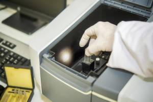
Specimen Preparation & Placement
Prepare sample as per requirement and place in push-rod dilatometer holder.
1Furnace & Push-Rod Setup
Enclose specimen in furnace; ensure push rod contacts specimen end.
2Controlled Heating & Measurement
Heat at programmed rate and measure linear expansion.
3Data Analysis
Calculate CTE from expansion vs. temperature data (reference sample optional).
4Technical Specifications
| Parameter | Details |
|---|---|
| Applicable Materials | Rigid solids (metals, ceramics, polymers) |
| Minimum CTE | > 0.5 µm/m·°C |
| Standard Temperature Range | -180 °C to 900 °C |
| Extended Range (Alumina Rod) | Up to 1600 °C |
| Extended Range (Graphite Rod) | Up to 2500 °C |
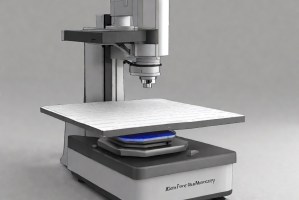
Instrumentation Used for Testing
- Push-rod dilatometer (horizontal or vertical configuration)
- Cylindrical programmable furnace
- Vitreous silica, alumina, or graphite push rods
- Displacement sensor system (LVDT or equivalent)
- Temperature measurement system (thermocouples)
- Data acquisition and analysis software
- Reference sample holder (dual-channel systems)
Results and Deliverables
- Coefficient of linear thermal expansion (CTE) value
- Specified temperature range for reported CTE
- Expansion vs. temperature curve
- Comparative material evaluation reports
Frequently Asked Questions
Case Studies
In-depth examination of genuine material testing solutions
Dopant and Ultra-Low Concentration Elemental Analysis Using STEM…
Dopant and Ultra-Low Concentration Elemental Analysis Using STEM…
Introduction to STEM-EELS for Elemental Analysis Scanning Transmission Electron Microscopy (STEM) combined with Electron Energy Loss...
Read Case StudyAnalysis of PVC Pipe Degradation Using FTIR Spectroscopy

Analysis of PVC Pipe Degradation Using FTIR Spectroscopy
PVC Pipe in Infrastructure — and Why Degradation Matters Polyvinyl chloride (PVC) pressure pipe is one...
Read Case StudyNano-scale roughness measurement of Si-wafers by Atomic Force…
Nano-scale roughness measurement of Si-wafers by Atomic Force…
Nano-scale surface roughness is a critical parameter in fabricated thin-films that are used in optics, solar...
Read Case Study
Request a Quote
Submit your material details and receive testing procedures, pricing, and turnaround time within 24 hours.
 Quick Turnaround and Hasslefree process
 Confidentiality Guarantee
 Free, No-obligation Consultation
 100% Customer Satisfaction
