


Transmission Line Pulse TLP ESD Guide Testing Services
Accredited transmission line pulse TLP ESD guide testing from Infinita Lab, performed to the exact standard requirements - accurate, reproducible results with full documentation for compliance, R&D, and quality control programs.
TRUSTED BY


Get compliant results - request your transmission line pulse TLP ESD guide testing quote
- Overview
- Scope, Applications, and Benefits
- Test Process
- Specifications
- Instrumentation
- Results and Deliverables
What Is Transmission Line Pulse TLP ESD Guide?
Transmission Line Pulse, or TLP, testing is the workhorse technique engineers reach for when they need to know exactly how a semiconductor device behaves the moment an electrostatic discharge event hits it. Rather than simply passing or failing a part against a single stress level, a TLP system charges a length of transmission line to a known voltage and discharges it into the device under test as a short, controlled current pulse – then repeats that at progressively higher levels while recording the resulting current and voltage. Plotting those points builds a quasi-static I-V curve that reveals how a protection structure turns on, where it snaps back, how much current it can hold, and ultimately the current at which it fails. That curve is the real value of TLP: it doesn’t just tell you pass or fail, it tells you why.
Unlike most of the test methods in Infinita Lab’s catalogue, TLP is not defined by a single ASTM specification. It’s governed instead by the ESD Association and JEDEC, whose jointly developed and maintained standards – including ANSI/ESD STM5.5.1 for component-level TLP and the related very-fast TLP (vf-TLP) methods – set the pulse widths, rise times, and measurement windows that make results comparable across labs and vendors. TLP data is widely used to correlate with human-body-model (HBM) ESD performance, while vf-TLP, with its much faster rise time, is used to approximate charged-device-model (CDM) events. Because it applies calibrated pulses well below the thermal-destruction threshold seen in slower sweeps, TLP lets designers probe deep into the ESD operating region safely and repeatably. Infinita Lab connects manufacturers, foundries, and design teams with accredited partner labs equipped to run this testing correctly, whether the goal is protection-circuit qualification, technology benchmarking, or root-cause failure analysis.

Applications and Benefits of Transmission Line Pulse TLP ESD Guide Testing
Scope
- This service covers transmission line pulse (TLP) and very-fast TLP (vf-TLP) electrical characterisation of semiconductor devices, ICs, and discrete ESD protection structures.
- Testing follows industry-recognised ESDA/JEDEC methodologies, including ANSI/ESD STM5.5.1 for standard TLP and the related vf-TLP protocols for faster events.
- Pulse widths, rise times, and amplitude sweeps are configured to the device technology and the failure mechanism under investigation.
- Both component-level and wafer-level (on-chip) TLP measurements can be arranged depending on the stage of development.
- The scope extends to correlating TLP results with human-body-model (HBM) and, where applicable, charged-device-model (CDM) qualification data.
- Snapback, trigger voltage, holding voltage, on-resistance, and second-breakdown current are all characterised as part of a standard TLP sweep.
- Custom pulse conditions can be requested for research applications, technology node development, or investigative failure analysis.
- Testing supports a wide range of device types, from simple diodes and clamps to complex multi-finger ESD protection networks and full I/O cells.
- Pre- and post-stress electrical parametric checks are typically included to confirm whether a device has shifted or failed after a given pulse level.
- Results are delivered in a form suitable for design comparison, SPICE model extraction, or qualification reporting.
Applications
- Semiconductor design teams use TLP data to develop and tune on-chip ESD protection circuits before committing a design to silicon.
- Foundries and IDMs rely on TLP characterisation to benchmark process technologies and compare protection device options across nodes.
- Failure analysis engineers use TLP to reproduce and study soft or hard ESD failures observed during HBM or CDM qualification testing.
- IC qualification teams use TLP-derived It2 and trigger voltage data to predict how a device will perform against system-level ESD requirements.
- Automotive and industrial electronics suppliers apply TLP testing to verify robustness margins for components exposed to harsher handling environments.
- Product engineering groups use vf-TLP specifically to investigate CDM-related failures in high-speed I/O and RF circuitry.
- Contract manufacturers and test houses use TLP as an incoming or outgoing verification step for ESD-sensitive components.
Benefits
- Provides a fast, non-destructive way to sweep through many current levels on a single device without needing dozens of separate parts.
- Generates a full I-V curve rather than a single pass/fail data point, giving engineers real insight into device behaviour.
- Correlates well with HBM performance, allowing teams to predict qualification outcomes earlier in the design cycle.
- Shortens the design-debug loop by pinpointing the exact current and voltage at which a protection structure begins to degrade.
- Supports both component-level and technology-development testing, making it useful across the whole product lifecycle.
- Reduces the number of parts consumed during characterisation compared to traditional HBM zap-and-test methods.
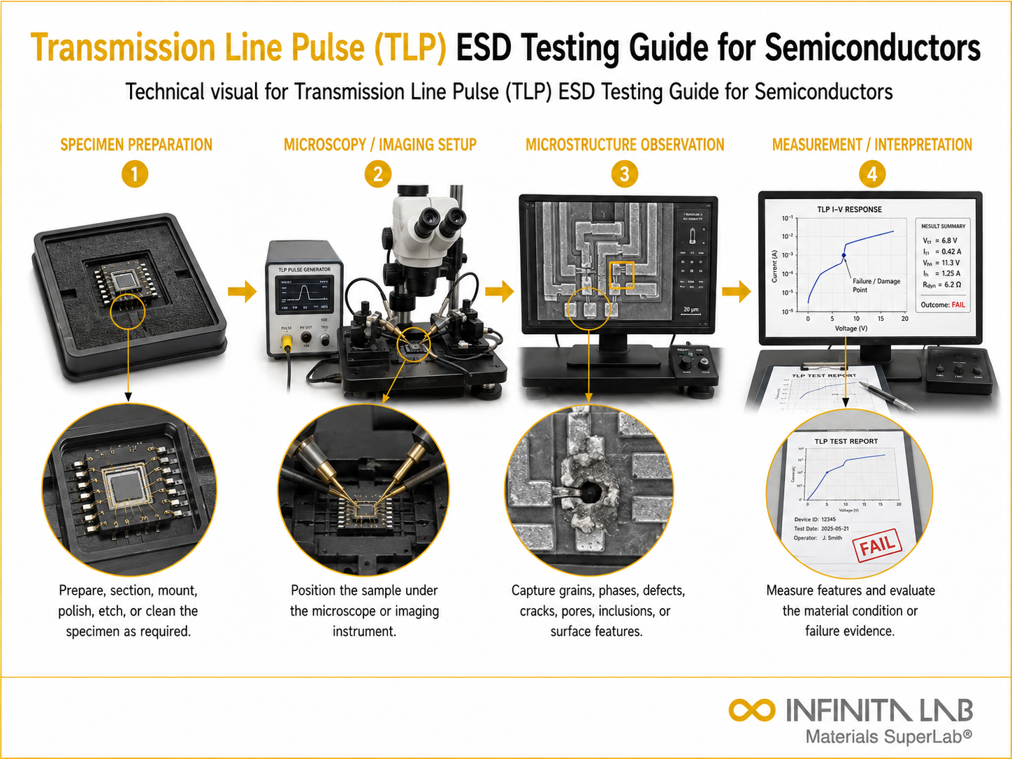
Transmission Line Pulse (TLP) Testing – Test Process
Device Preparation
The semiconductor device is mounted on a test fixture ensuring proper electrical contact and signal integrity.
1System Calibration
The TLP system is calibrated using reference loads to ensure accurate pulse width, amplitude, and current measurement.
2Pulse Application
Controlled rectangular pulses of defined width and amplitude are applied to the device under test.
3Data Analysis
Voltage-current response is recorded to determine breakdown behavior, failure thresholds, and safe operating limits.
4Test parameters and requirements
| Parameter | Details |
|---|---|
| Measurement Principle | Short-duration rectangular current pulse stress analysis |
| Pulse Width Range | 10 ns to 1000 ns adjustable |
| Current Range | Up to 100 A depending on system configuration |
| Voltage Range | Up to several hundred volts |
| Rise Time | < 10 ns for high-speed systems |
| Output Data | I-V characteristic curves under pulse stress |


- TLP Pulse Generator – Charges a transmission line to a set voltage and discharges it as a calibrated pulse into the device under test.
- Very-Fast TLP (vf-TLP) System – Delivers sub-nanosecond rise-time pulses used to approximate charged-device-model stress events.
- High-Bandwidth Oscilloscope – Captures incident and reflected voltage/current waveforms with the time resolution needed to resolve fast transients.
- Current and Voltage Probes – Provide accurate, wide-bandwidth measurement of the pulse response at the device terminals.
- Wafer Probe Station – Enables direct on-wafer TLP characterisation of test structures before packaging.
- Parametric Test Equipment – Performs pre- and post-stress DC parametric checks to detect leakage shifts or functional failures.
- Device Fixturing and Sockets – Holds packaged parts securely while maintaining signal integrity during pulse application.
Equipment and Instrumentation Used for Testing
What You Receive: Test Report, Data, and Certification
- A complete I-V characteristic curve for each device tested, showing trigger voltage, snapback, and holding behaviour.
- Extracted numerical parameters including trigger voltage, holding voltage, on-resistance, and second-breakdown failure current (It2).
- Pre- and post-stress parametric comparison data identifying any leakage shift or degradation at each pulse level.
- A summary report correlating TLP or vf-TLP results against the relevant HBM or CDM qualification target.
- Annotated waveform captures for key pulse levels, useful for design review or failure-analysis follow-up.
- Raw data exports suitable for SPICE model extraction or further in-house analysis by the client’s design team.
Transmission Line Pulse TLP ESD Guide FAQs
TLP testing is a high-speed electrical test method used to evaluate semiconductor device behavior under short-duration, high-current stress conditions that simulate electrostatic discharge events.
It identifies failure thresholds and breakdown points, helping engineers design robust ESD protection structures and prevent device failure in real-world electrical environments.
Unlike static measurements, TLP captures transient device behavior under fast pulse stress, revealing real switching, breakdown, and thermal effects that occur during ESD events, which static testing cannot replicate accurately.
It helps identify avalanche breakdown, second breakdown, thermal runaway, and snapback behavior, which are critical for understanding failure mechanisms under high current density conditions.
TLP generates controlled rectangular pulses with defined rise time and width, closely replicating the fast energy transfer characteristics of real ESD events while maintaining measurement control and repeatability.
TLP stands for Thermal Laser Photometry in materials testing. The test uses laser-based thermal measurements to evaluate material properties such as thermal conductivity or diffusivity.
A TLP lab test uses a controlled laser or thermal source to heat a sample and measures its thermal response. The results are analyzed to determine the material’s thermal properties.
In medical applications, TLP can refer to different tests depending on the context. The specific procedure and purpose depend on what TLP represents in the medical test being performed.
Why Choose Infinita Lab for Transmission Line Pulse TLP ESD Guide Testing
When your Transmission Line Pulse TLP ESD Guide results have to hold up - for compliance, a customer audit, or an engineering decision - accuracy and an unbiased third-party report matter more than price. Infinita Lab routes your transmission line pulse TLP ESD guide testing to ISO/IEC 17025-accredited U.S. partner labs with hands-on method experience, so you get defensible data, transparent reporting, and turnaround times built around your project deadline - not ours.

Looking for an Accredited Partner for Transmission Line Pulse TLP ESD Guide Testing?
Send query us at hello@infinitalab.com or call us at (888) 878-3090 to learn more about our services and how we can support you.



Request a Quote
Submit your material details and receive testing procedures, pricing, and turnaround time within 24 hours.
 Quick Turnaround and Hasslefree process
 Confidentiality Guarantee
 Free, No-obligation Consultation
 100% Customer Satisfaction
