


ASTM E1681 Threshold Stress Intensity Testing for Environment-Assisted Cracking
ASTM E1681 test method is used to determine the environment-assisted cracking threshold stress intensity factor parameters, KIEAC and KEAC, for metals from constant-force testing of fatigue pre-cracked beam or compact fracture specimens and constant-displacement testing of fatigue pre-cracked bolt-load compact fracture specimens.

TRUSTED BY


Precision-driven testing for dimensional accuracy and compliance
- Overview
- Scope, Applications, and Benefits
- Test Process
- Specifications
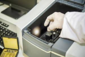
- Instrumentation
- Results and Deliverables
Overview
The ASTM E1681 standard specifies the determination of the environment-assisted cracking threshold stress-intensity factor, KIH, in a hydrogen environment. ASTM E1681 differentiates between two main types of loading: either the specimen is loaded under constant displacement over a specified time period, or under continuous force. In some instances, this may lead to crack growth or fracture, but that is not always the case.
A testing machine is not required for constant displacement KIH testing (constant displacement). The specimen is bolt-loaded under a certain constant displacement in an inert environment.

Scope, Applications, and Benefits
Scope
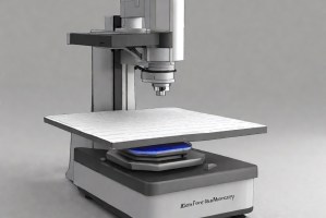
ASTM E1681 provides a standard guide for qualitative elemental analysis using Scanning Electron Microscopy with Energy Dispersive X-ray Spectroscopy (SEM-EDS). To determine the elemental composition of materials, it describes recommended procedures for instrument setup, sample preparation, data acquisition, and interpretation. The approach is commonly used for failure analysis and material characterization and is primarily qualitative and semi-quantitative.
Applications
- Failure analysis and root cause investigations
- Material identification and verification
- Quality control and contamination analysis
- Metallurgical and microstructural studies
- Semiconductor and electronic component analysis
Benefits
- Enables rapid qualitative identification of elements in solid materials
- Supports micro-area and localized analysis
- Non-destructive or minimally destructive testing
- Applicable to a wide range of materials and sample types
- Enhances consistency and reliability of SEM-EDS results
Testing Process
Sample Selection
Select a representative, clean specimen suitable for SEM analysis
1Sample Preparation
Mount the specimen and apply a conductive coating if required
2Instrument Setup
Configure SEM accelerating voltage, beam current, and working distance
3Reporting
Document identified elements and analysis conditions
4Technical Specifications
| Parameter | Details |
|---|---|
| Analysis Type | Qualitative / Semi-quantitative elemental analysis |
| Sample State | Solid, vacuum-compatible |
| Accelerating Voltage Range | 5–30 kV |
| Vacuum Requirement | High vacuum (low vacuum optional if supported) |
| Data Output | EDS spectra, elemental peak identification |


Instrumentation Used
- Fatigue testing machine or servo-hydraulic test system
- High-accuracy load cell
- Crack length measurement system (compliance, optical, or potential drop method)
- Environmental test chamber or corrosion cell
- Temperature and environmental control system
- Data acquisition and analysis software
Results and Deliverables
- Identifies the elements present in the analyzed regions of the specimen
- Confirms elemental distribution at selected micro-areas
- Detects foreign elements or contaminants, if present
- Provides characteristic X-ray spectra for each analyzed area
- Enables comparison of elemental composition between samples or regions
- Supports material verification and conformity assessment
Frequently Asked Questions
Why Choose Infinita Lab for Advanced Materials Testing and Characterization?
At the core of this breadth is our network of 2,000+ accredited laboratories across the USA, offering access to over 10,000 testing methods and analytical services. From advanced materials characterization (SEM, TEM, RBS, XPS) to mechanical, chemical, environmental, biological, and standardized ASTM/ISO-compliant testing, we deliver unmatched flexibility, specialization, and scale. You are never limited by geography, facility, or methodology — Infinita Lab connects you to the right expertise and testing solution, every time.

Looking for a Trusted Partner for Accurate and Reliable Testing Services?
Send query us at hello@infinitlab.com or call us at (888) 878-3090 to learn more about our services and how we can support you.

Request a Quote
Submit your material details and receive testing procedures, pricing, and turnaround time within 24 hours.
 Quick Turnaround and Hasslefree process
 Confidentiality Guarantee
 Free, No-obligation Consultation
 100% Customer Satisfaction
